WHY INSTALL HEAT INSULATION ?
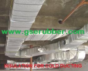
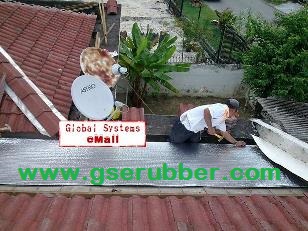
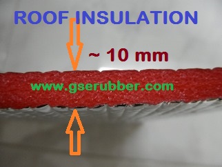
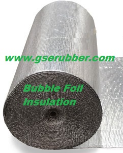
Insulating your home will save energy and provide a healthier and more comfortable indoor environment. The heat captured from the sun or generated by your heater needs to be stopped from escaping through walls, ceilings and floors. Insulated surfaces are warmer. Condensation is less likely to form on them so there is less mould and mildew. In summer insulation will keep the heat out, making your home cooler. Insulation will provide a more even temperature year round. The initial investment of installing higher insulation than the Building Code prescribes will pay off over time because you save money in energy bills. Older homes often have little or no insulation but they can be retrofitted, making them much more comfortable and saving energy for heating. The payback period for installing ceiling insulation, for example, is about 5 years or even shorter. However the main motivation behind installing insulation is often the added comfort and warmth, rather than financial savings. How does it work? Most insulation works by trapping air in cavities. The smaller the cavities of trapped air, the better the insulation material will work. Good examples in nature are animal shelters, such as bird’s nests, which have the ability to keep eggs and young birds at an even temperature in extreme weather conditions. The birds themselves have an added layer of insulation provided by their feathers. Humans have learned from nature’s example and clothes have been used for thousands of years to provide warmth. We can insulate our homes by providing cavities of still air, such as in wall insulation or double-glazing. This reduces heat transfer because air is a poor conductor of heat. Another method is to use surfaces that reflect heat, such as silver foil behind radiators.
1 ) Why Insulate & Grade ?
Better understanding explained below
Better understanding explained below
2 ) ASTM test standard and UL 94 Defination
A ) ASTM D1622 - 08 Standard Test Method for Apparent Density of Rigid Cellular Plastics
Significance and Use
If the material to be tested includes forming skins, the apparent overall density, or the apparent core density, or both, shall be determined. If the material does not have forming skins, the term overall density is not applicable.
This test method is also applicable to spray foam materials.
Before proceeding with this test method, reference shall be made to the specification of the material being tested. Any test specimen preparation, conditioning, dimensions, or testing parameters, or combination thereof, covered in the relevant ASTM materials specification shall take precedence over those mentioned in this test method. If there are no relevant ASTM material specifications, then the default conditions in this method apply.
1. Scope
1.1 This test method covers the density of a cellular plastic. Density can be evaluated as the apparent overall density (includes forming skins) or by apparent core density (forming skins removed).
B ) ASTM C177-97 Standard Test Method for Steady-State Heat Flux Measurements and Thermal Transmission Properties by Means of the Guarded-Hot-Plate Apparatus
1. Scope
1.1 This test method establishes the criteria for the laboratory measurement of the steady-state heat flux through flat, homogeneous specimen(s) when their surfaces are in contact with solid, parallel boundaries held at constant temperatures using the guarded-hot-plate apparatus.
1.2 The test apparatus designed for this purpose is known as a guarded-hot-plate apparatus and is a primary (or absolute) method. This test method is comparable, but not identical, to ISO 8302.
1.3 This test method sets forth the general design requirements necessary to construct and operate a satisfactory guarded-hot-plate apparatus. It covers a wide variety of apparatus constructions, test conditions, and operating conditions. Detailed designs conforming to this test method are not given but must be developed within the constraints of the general requirements. Examples of analysis tools, concepts and procedures used in the design, construction, calibration and operation of a guarded-hot-plate apparatus are given in Refs ().
1.4 This test method encompasses both the single-sided and the double-sided modes of measurement. Both distributed and line source guarded heating plate designs are permitted. The user should consult the standard practices on the single-sided mode of operation, Practice C 1044, and on the line source apparatus, Practice C 1043, for further details on these heater designs.
1.5 The guarded-hot-plate apparatus can be operated with either vertical or horizontal heat flow. The user is cautioned however, since the test results from the two orientations may be different if convective heat flow occurs within the specimens.
1.6 Although no definitive upper limit can be given for the magnitude of specimen conductance that is measurable on a guarded-hot-plate, for practical reasons the specimen conductance should be less than 16 W/(m 2K).
1.7 This test method is applicable to the measurement of a wide variety of specimens, ranging from opaque solids to porous or transparent materials, and a wide range of environmental conditions including measurements conducted at extremes of temperature and with various gases and pressures.
1.8 Inhomogeneities normal to the heat flux direction, such as layered structures, can be successfully evaluated using this test method. However, testing specimens with inhomogeneities in the heat flux direction, such as an insulation system with thermal bridges, can yield results that are location specific and shall not be attempted with this type of apparatus. See Test Methods C 976 or C 236 for guidance in testing these systems.
1.9 Calculations of thermal transmission properties based upon measurements using this method shall be performed in conformance with Practice C 1045.
1.10 In order to ensure the level of precision and accuracy expected, persons applying this standard must possess a knowledge of the requirements of thermal measurements and testing practice and of the practical application of heat transfer theory relating to thermal insulation materials and systems. Detailed operating procedures, including design schematics and electrical drawings, should be available for each apparatus to ensure that tests are in accordance with this test method. In addition, automated data collecting and handling systems connected to the apparatus must be verified as to their accuracy. This can be done by calibration and inputting data sets, which have known results associated with them, into computer programs.
1.11 It is not practical for a test method of this type to establish details of design and construction and the procedures to cover all contingencies that might offer difficulties to a person without technical knowledge concerning theory of heat flow, temperature measurements and general testing practices. The user may also find it necessary, when repairing or modifying the apparatus, to become a designer or builder, or both, on whom the demands for fundamental understanding and careful experimental technique are even greater. Standardization of this test method is not intended to restrict in any way the future development of new or improved apparatus or procedures.
1.12 This test method does not specify all details necessary for the operation of the apparatus. Decisions on sampling, specimen selection, preconditioning, specimen mounting and positioning, the choice of test conditions, and the evaluation of test data shall follow applicable ASTM Test Methods, Guides, Practices or Product Specifications or governmental regulations. If no applicable standard exists, sound engineering judgment that reflects accepted heat transfer principles must be used and documented.
1.13 This test method allows a wide range of apparatus design and design accuracy to be used in order to satisfy the requirements of specific measurement problems. Compliance with this test method requires a statement of the uncertainty of each reported variable in the report. A discussion of the significant error factors involved is included.
1.14 The values stated in SI units are to be regarded as the standard. The values given in parentheses are for information only. Either SI or Imperial units may be used in the report, unless otherwise specified.
C ) ASTM E96 / E96M - 05 Standard Test Methods for Water Vapor Transmission of Materials
Significance and Use
The purpose of these tests is to obtain, by means of simple apparatus, reliable values of water vapor transfer through permeable and semipermeable materials, expressed in suitable units. These values are for use in design, manufacture, and marketing. A permeance value obtained under one set of test conditions may not indicate the value under a different set of conditions. For this reason, the test conditions should be selected that most closely approach the conditions of use. While any set of conditions may be used and those conditions reported, standard conditions that have been useful .
1. Scope
1.1 These test methods cover the determination of water vapor transmission (WVT) of materials through which the passage of water vapor may be of importance, such as paper, plastic films, other sheet materials, fiberboards, gypsum and plaster products, wood products, and plastics. The test methods are limited to specimens not over 11/ 4 in. (32 mm) in thickness except as provided in Section . Two basic methods, the Desiccant Method and the Water Method, are provided for the measurement of permeance, and two variations include service conditions with one side wetted and service conditions with low humidity on one side and high humidity on the other. Agreement should not be expected between results obtained by different methods. The method should be selected that more nearly approaches the conditions of use.
1.2 The values stated in inch-pound units are to be regarded separately as the standard. Within the text, the SI units are shown in parentheses. The values stated in each system are not exact equivalents; therefore each system must be used independently of the other. Combining values from two systems will result in non-conformance with the standard. However derived results can be converted from one system to other using appropriate conversion factors .
D ) ASTM C209 - 07ae1 Standard Test Methods for Cellulosic Fiber Insulating Board
Significance and Use
The test methods contained in this document are intended for cellulosic fiber insulating board as described in Specification C 208. These test methods examine mechanical, physical and thermal properties, properties related to water absorption and water vapor exposure, and flammability related properties.
The results of these tests may be used to describe the performance of insulating board and are suitable for use in material specifications.
Note 1—Committee C-16 is in the process of splitting this document into discrete test methods categorized by the nature of the test methods.
1. Scope
1.1 These test methods cover those insulation products in specified Specification C 208 that are not singularly specified elsewhere as insulating formboard (see Specification C 532) and nail-base sheathing (see Specification D 2277). The requirements for the products' physical properties are specified in Specification C 208. The methods for the general insulation products' physical properties are given as follows:
1.2 Reference is provided to an established source for nomenclature and definitions.
This standard does not purport to address all of the safety concerns, if any, associated with its use. It is the responsibility of the user of this standard to establish appropriate safety and health practices and determine the applicability of regulatory limitations prior to use.
1.3 Several of the test methods contained in this document are referenced by material specifications other than cellulosic fiber insulating board. These include mineral fiber, perlite, polyisocyanurate, polystyrene and phenolic materials.
E ) ASTM G21-96 Standard Practice for Determining Resistance of Synthetic Polymeric Materials to Fungi
1. Scope
1.1 This practice covers determination of the effect of fungi on the properties of synthetic polymeric materials in the form of molded and fabricated articles, tubes, rods, sheets, and film materials. Changes in optical, mechanical, and electrical properties may be determined by the applicable ASTM methods.
F ) ASTM D1149 - 07 Standard Test Methods for Rubber Deterioration-Cracking in an Ozone Controlled Environment
Significance and Use
The significance of these test methods lies in the ability to differentiate between the degrees of ozone resistance under the limited and specified conditions of the accelerated tests. The degree of resistance being judged by the appearance and magnitude of the formation of cracks in the surface of the subject material.
In service, rubber materials deteriorate when exposed to ozone. It is imperative to have test methods in which simple, accelerated time/exposure, comparisons of the material’s ability to resist cracking caused by ozone exposure can be empirically evaluated. Such tests can be used for producer/consumer acceptance, referee purposes, research, and development.
These methods are not necessarily suited for use in purchase specifications as there may be no correlation with service performance as actual service conditions (outdoor exposure) vary widely due to geographic location and, therefore, may not yield repeatable or reproducible results.
1. Scope
1.1 These test methods are used to estimate the effect of exposure, under surface tensile strain conditions, either dynamic or static, in an atmosphere containing specified levels of ozone concentration, expressed as partial pressure (refer to Note 1), on vulcanized rubber, rubber compounds, molded or extruded soft rubber, and other specified materials, or as may be determined empirically. The effect of naturally occurring sunlight or light from artificial sources is excluded.
1.2 Previously published ASTM documents Test Method D 518 and Test Methods D 3395 have been included in these test methods, D 1149, in 2007.
1.2.1 Test Method D 518 and Test Methods D 3395 have henceforth been withdrawn and superseded by Test Methods D 1149. When Test Methods D 1149 is cited, or otherwise referenced, a notation shall be included to this effect. Please refer to section for the appropriate references.
1.3 The specified conditions of exposure to ozone in the controlled environments are accelerated in comparison to outdoor exposure. These accelerated ozone test methods may not give results which correlate with outdoor exposure tests or service performance.
1.4 All materials, instruments, or equipment used for the determination of mass, force, dimension, ozone concentration, partial pressure, temperature, velocity, and gas exchange rate shall have direct traceability to the National Institute for Standards and Technology, or other internationally recognized organization parallel in nature.
G ) UL 94 Standard
Tests for Flammability of Plastic Materials for Parts in Devices and Appliances UL 94
1 Scope
1.1 These requirements cover tests for flammability of polymeric materials used for parts in devices and appliances. They are intended to serve as a preliminary indication of their acceptability with respect to flammability for a particular application.
1.1 revised June 2, 2006
1.2 The methods described in this Standard involve standard size specimens and are intended to be used solely to measure and describe the flammability properties of materials, used in devices and appliances, in response to a small open flame or radiant heat source under controlled laboratory conditions.
1.2 revised June 2, 2006
1.2.1 The tests in the Standard for Tests for Flammability of Small Polymeric Component Materials should be used to evaluate small components which contain materials that can not be fabricated into standardized specimens in the minimum use thickness and subjected to applicable preselection tests in UL 94. Test procedures in UL 1694 are applicable to small components with an overall volume of less than 2500 mm3 (0.15 in3). UL 1694 is generally not applicable to small components with an overall volume greater than 2500 mm3 (0.15 in3).
1.2.1 added June 2, 2006
1.3 The final acceptance of the material is dependent upon its use in complete equipment that conforms with the standards applicable to such equipment. The flammability classification required of a material is dependent upon the equipment or device involved and the particular use of the material. The performance level of a material determined by these methods shall not be assumed to correlate with its performance in end-use application. The actual response to heat and flame of materials depends upon the size and form, and also on the end-use of the product using the material. Assessment of other important characteristics in the end-use application includes, but is not limited to, factors such as ease of ignition, burning rate, flame spread, fuel contribution, intensity of burning, and products of combustion.
1.3 revised June 2, 2006
1.4 If found to be appropriate, the requirements are applied to other nonmetallic materials.
1.4 revised June 10, 1997
1.5 These tests, with the exception of the Radiant Panel Test in Section 10, are not applicable to the evaluation of parts where the thickness exceeds 13.0 mm or where the surface area exceeds 1 m2. These requirements do not cover polymeric materials when used for building construction, finishing, or contents such as wall and floor coverings, furnishings, decorative objects and so forth. In addition, the fire resistance (in terms of an hourly rating), flame spread, smoke characterization, and heat release rate is not evaluated. Other fire tests exist and shall be used to evaluate the flammability of materials in the intended end-use-product configuration.
1.5 revised June 2, 2006
The UL 94 Standard provides a method for rating the ignition characteristics of plastic materials. Two UL 94 ratings that code officials commonly run across are HB and V (V-0, V-1, or V-2). These ratings are established using small-scale tests in which approximately 5 by 1/2 inch samples are subject to a 3/4 inch, 50W tirrel burner flame ignition source. To achieve a HB rating, test samples, placed horizontally, burn slowly across the sample when the test flam is applied to the end of the sample. To achieve a V rating (e.g. V-2, V-1, or V-0) the test samples, placed vertically with the test flame impinging on the bottom of the sample, must extinguish withtin specified times, not burning to the top clamp or dripping molten material which ignites a cotton indicator.
UL has tested literally thousands of materials for UL 94 ratings, which are widely published in manufacturers’ literature. The customers for these materials are primarily the end-use manufacturers of electrical equipment and products that are required to use UL 94 rated materials in their factory production.
Copyright © GSE ONLINE SDN BHD ( 1116968-P ) ALL RIGHTS RESERVED


